 |
|||
|
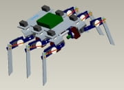
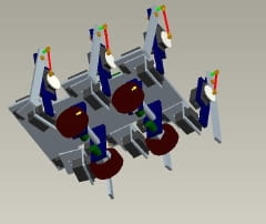
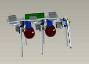
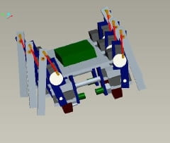
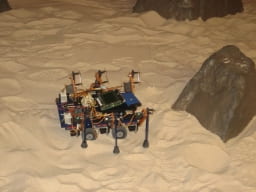
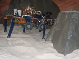
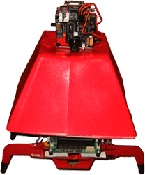
About the ByroBot The main idea behind the hardware component of this research project is to design, build, and control a low-cost mobile robot that can use both legs and wheels. Some of the legged-wheeled robots that currently exist have their wheels attached to an actuator located at the end of the robot leg. When the robot is commanded to walk, the wheel is stationary and the robot actually walks on its wheel. This causes a number of problems that hinders long-term and robust operation in remote environments. The ByroBot was designed with 6 legs and 4 wheels. Each leg has 3 servo motors to provide 3 degrees-of-freedom for instituting a walking pattern. Each wheel is attached to a DC motor for 4-wheel drive. The robot body material is polycarbonate plastic (which is nice and robust, and more lightweight than aluminum or some other metal). The robot is able to drive on its 4 wheels and roll over obstacles, as well as have the legs retract up (as you see in the CAD model and in the videos), so it can stand and walk in its legged configuration for navigating over larger obstacles. The Eyebot is the primary controller for this robot. It can be programmed in either C or Assembler language. An additional controller, the Servo Controller, is interfaced with the Eyebot to allow control of up to 32 servo channels. The Eyebot and the Servo Controller are able to communicate through their serial COM ports using a female-to-female null modem. When ByroBot stands, it is primarily supported by the high-torque servos that are at the “hip joint” of each leg. Joint torques were calculated to determine the torque needed for theses servos so that ByroBot could support itself standing. Kinematic analysis is done for the wheels to find velocity and position data, as well as the radius of curvature of the robot motion using different linear velocity of the wheel pairs in its differential drive. Forward kinematic analysis was also done for the legs to find their “foot” positions based on the servo motor angles, which controls the joint positions. By locating the position of the feet that are in contact with the ground, a polygon of support can be determined for the robot while standing. Keeping the robot body center of mass inside this polygon of support at all times while walking will allow for optimum stablility of the Byrobot. Why do we want these specifications? CAD Images
In Action
|
|||
| About | Perception and Reasoning | Human-System Interaction | Space and Field Robotics | People | Home | |||
<![CDATA[
]]>


